Attaching the Sensors
SK7 provides connections for up to 8 sensor inputs. The “odd” numbered pins are sensor inputs 1-8; the “even” numbered pins are all ground. The sensor is considered active (occupied) if its input voltage is more than around 8v.
A power source is available from the power connector, SK1. SK1 pin 3 provides approximately +12v which may be used for sensors to switch onto the sensor inputs, as described below.
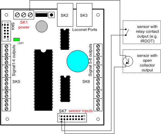
- Sensors with “relay contact” outputs e.g. IRDOT can be connected between the sensor input and SK1 pin 3. When the sensor is active, the relay connects +12v to the sensor input.
- Sensors with “open collector” outputs can be connected between the sensor input and SK1 pin 3. In some circumstances. When the sensor is active, the transistor allows a current to flow into the sensor input. HOWEVER it is important that the “open collector” output are also electrically isolated from each other: there must be no common connection between the “emitters” of the transistors. This will depend on the design of the sensor itself.
- If the output is from an opto isolator, it will probably connect OK.
Programming the SIGM20
The SIGM20 inputs need to be selected to generate sensor messages. The settings are normally programmed using the Locoanalyse application for a PC. The sensor information is programmed using the SIGM20 editing form:
|
Form item |
Programming |
|
Sensor Board Number |
Choose a number between 1 and 255. This must be different from the number assigned to any BDL168 or SE8c boards. |
|
On-board inputs |
Sets how the sensor inputs are used. Choose “Sensor numbers 1-8” or “sensor numbers 9-16”. |