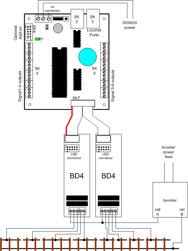
The SIGM20 has 8 sensor inputs that can be connected via SK7. These inputs can be connected to detectors from many sources.
Digitrax supply a four input block detector, the BD4, that works well with the SIGM20. Up to two BD-4 units can be connected to provide 8 block detect sections. The BD4 operates by sensing the current flow to the rails. The track has to be isolated, into sections; the current to each section is provided through the BD4. When it senses a current drawn by a decoder, it signals the SIGM20.
Connecting the BD-4
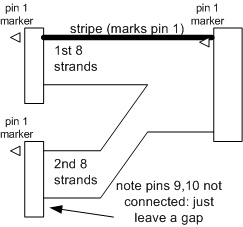
The BD4 outputs are connected using its plug DS-1. This connects to the SIGM20 SK7. A 20 way ribbon cable from The SIGM20 can be simply split into two, to connect to two BD4 boards. It connects to the connector marked “DS1” on the BD4.
| SIGM20 SK7 pin | 1st BD4 DS1 pin | 2nd BD4 DS1 pin |
| 1 | 1 | |
| 3 | 3 | |
| 5 | 5 | |
| 7 | 7 | |
| 2,4,6&8 | 2,4,6&8 | |
| 9 | 1 | |
| 11 | 3 | |
| 13 | 5 | |
| 15 | 7 | |
| 10,12,14&16 | 2,4,6&8 |
A suitable cable can be purchased from Sig-naTrak® as part number “CP_SIGM20” here
Connecting the cables
Programming the SIGM20
The SIGM20 inputs need to be selected to generate sensor messages. The settings are normally programmed using the Locoanalyse application for a PC.
|
Form item |
Programming |
|
Sensor Board Number |
Choose a number between 1 and 255. This must be different from the number assigned to any BDL168 or SE8c boards. |
|
On-board inputs |
Sets how inputs from the BD4 are used. Choose “Sensor numbers 1-8” or “sensor numbers 9-16” when connected to a BD-4 |