To be able to establish the signal configuration, the following need to be known and documented before programming can start. See the examples on the next page:
- The exact track configuration;
- Allocation of point numbers;
- Knowledge of point direction: which is CLOSED and which is THROWN;
- Knowledge of block detector numbers, and where the track cuts are;
- Knowledge of where the signals are to be, and which direction they face.
- Knowledge of the type of model signal head used at each location, to decide how it needs to be connected. There are several different kinds of model available; it is unlikely that all masts on a large layout would be of the same type.
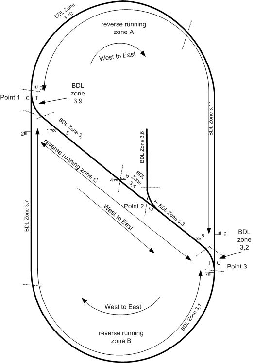
This is a simple example, with three points, one BDL16 block detector and ten signals. The number of signals is high because the track can run in any direction.
Allocate Numbers
The layout has only a small number of points, controlled by a DS54. These are numbered 1-4. The SIGM20 numbers must avoid all point number. In this case an address of 201 has been picked for the first signal: this means the board will occupy addresses 201-216.
Decide Where to Put the Signals
A starting principle can be “put them where the prototype railway would have them”. However, this may not be practical because of space constraints: the signals need in general to be spaced apart by at least the length of the longest train that is to be run.
In this example, the following thought process was followed:
- A signal would be added at each possible entrance to a point on the oval, because another train could be blocking the path. This defines a need for signals 1,2,3,6,7 & 8.
- A signal at the intermediate part of the reversing loop was added to allow a train to be halted if the point 2 on the reverse loop was set against it. This defined a need for signal 5, and signal 4 was added to control trains in the opposite direction. [There is no real need for this signal; it was just added as an example].
Decide the Reverse Running Zones
Many railways will not need to worry about reverse running zones. However, if there is a need to run trains in both directions on any given piece of track, then the reverse running zones provide a method to control the running direction of the track automatically.
Reverse Running Zones define a region of track in which train operations will happen in one direction at a time. This region could be small or large, and could in principle hold several trains. The zone is used to inform the signals or the direction of train operations.
It is important to define carefully where each zone starts and ends, and to determine which direction is which. The SIGM10 assigns the running direction to be either West-to-East or East-To-West. It is arbitrary which direction is chosen as West-to-East, but is important to record the decision!
In this layout there are three distinct track sections. In each section the running direction can be independently set. So the zones have been defined to be:
- Zone A: the top half of the oval. West-to-East is defined as clockwise running.
- Zone B: the bottom half of the oval. West-to-East is defined as clockwise running.
- Zone C: the reverse loop across the layout. West-to-East is defined as top left to bottom right.
- Note that points 1 and 3 are not part of either zone.
Determine Signal Logic
Each signal needs to have several pieces of information programmed into it. These include:
- The type of model signal mast used;
- Which reverse running zone the signal belongs to (if any);
- The number of the next signal ahead of the current signal;
- The signal type (block or diverging junction);
- The point number for diverging junction signals;
- The block occupancy detectors for the block ahead;
- The logic that would make the signal go red.
The settings for this layout can be summarised in a table:
|
Sig-nal |
Type |
Point No. |
Reverse zone |
Next signal |
Block Occupancy Conditions |
Red Conditions |
|
1 |
Block |
N/A |
C, E-W |
9 |
3,9 or 3,10 |
Red if point 1 Closed |
|
2 |
Block |
N/A |
B, W-E |
9 |
3,9 or 3,10 |
Red if point 1 Thrown |
|
3 |
Diverging |
1 |
A, E-W |
7 if C 5 if T |
3,1 or 3,9 or 3,7 if C 3,5 or 3,9 if T |
None |
|
4 |
Block |
N/A |
C, E-W |
1 |
3,5 |
None |
|
5 |
Block |
N/A |
C, W-E |
8 |
3,4 or 3,3 |
Red if point 2 Thrown |
|
6 |
Block |
N/A |
A, W-E |
2 |
3,2 or 3,1 or 3,7 |
Red if point 3 Thrown |
|
7 |
Diverging |
3 |
B, E-W |
10 if C 4 if T |
3,2 or 3,11 if C 3,2 or 3,3 or 3,4 if T |
None |
|
8 |
Block |
N/A |
C, W-E |
2 |
3,2 or 3,1 or 3,7 |
Red if point 3 Closed |
Examples
- Signal 4 is probably the simplest cases that could be considered. They are simple block signals; they need no other logic than block detector numbers and the next signal numbers.
- Signal 5 adds a simple condition to make the signal red if point 2 is set to Thrown. This is because a train passing the signal if that point is thrown would derail on the point, because it would be set against it.
- Signals 1,2,6 and 8 have similar logic conditions because a train passing them would immediately run into the point.
- Signals 7 and 3 are at the entry to a diverging junction: the route ahead can be one of two paths depending on the setting of the point. Both signals are therefore programmed as “diverging junction” signals dependent on the state of points 3 and 1 respectively. Consider signal 3:
- If point 1 is closed, the train continues around the oval; the next signal reached is number 7. The block occupancy is determined by sensor numbers 3,7 and 3,1.
- If point 1 is thrown, the train takes the reverse look and the next signal reached is 5. The block occupancy is determined by sensor number 3,5.
Determine Reverse Running Zone Logic
The last phase is to determine how the reverse run zone logic will work. This may be completely automatic, or manual intervention may be needed sometimes.
Each zone has three key pieces of information:
- West-to-East conditions. These conditions if true will try to make the zone direction change to West-to-East. Typically these conditions would be detect a train trying to enter the zone at the West end of the zone.
- East-to-West conditions. These conditions if true will try to make the zone direction change to East-to-West. Typically these conditions would be detect a train trying to enter the zone at the East end of the zone.
- Freeze conditions. These conditions if true will stop the zone from changing state. Typically these conditions would detect the presence of a train within the zone: usually the running direction would not be automatically changed when the zone was occupied.
- Note that the direction will only change when an unambiguous decision can be mode.
There is also an extra state called “shunting” mode where the zone behaves as though it is reverse running in both directions. Typically this would be entered under manual control. A small number of conditions is used to enter “shunting” state: these would normally detect an “unused” point number that the user activated (e.g. by setting point 678 to Thrown) to force the zone into “shunt”.
The required logic can be summarised:
|
Zone |
Condition Group |
Logic required |
|
A |
Go To E-to-W if |
Sensor 3,7 occupied AND Point 3C AND zone B running E-W |
|
Go to W-to-E if |
(Sensor 3,7 occupied AND Point 1C AND zone B running W-E) or (Sensor 3.5 occupied AND Point 1T AND zone C running E-W) |
|
|
Don’t change if |
Sensor 3,10 occupied or Sensor 3.11 occupied |
|
|
B
|
Go To E-to-W if |
Sensor 3,10 occupied AND Point 1C AND zone A running E-W |
|
Go to W-to-E if |
(Sensor 3,3 occupied AND Point 3T AND zone C running W-E) or (Sensor 3,11 occupied AND Point 3C AND zone A running W-E) |
|
|
Don’t change if |
Sensor 3,1 occupied or Sensor 3,7 occupied |
|
|
C
|
Go To E-to-W if |
Sensor 3,1 occupied AND Point 3T AND zone B running E-W |
|
Go to W-to-E if |
Sensor 3,10 occupied AND Point 1T AND zone A running E-W |
|
|
Don’t change if |
Sensor 3.5 occupied or Sensor 3.4 occupied or Sensor 3.3 occupied |
To understand how this is derived, consider zone A.
Its “don’t change if” condition is easy: this is simply defined to be true if any of the sensors detecting a train in the zone are occupied. This will stop the direction changing automatically when there is a train in the zone. So the required logic is “don’t change if: Sensor 3,10 occupied or Sensor 3.11 occupied”
Its “go to East-to-West” condition is more complicated. A change to “East-to-West” is needed if a train is entering the zone from the vicinity of point 3. This will happen when three conditions are all met at the same time:
- Sensor 3,7 is occupied. This tells us there is a train in the bottom part of the oval;
- Point 3 is set to CLOSED. This means the train arriving at the point 3 will continue around the oval;
- Zone B is running East-to-West (i.e. the train will be approaching point 3 travelling anticlockwise).
- Because we need all three conditions to happen at the same time, the “and with next” option is selected for the first two conditions. The logic therefore reads “Sensor 3,7 occupied AND Point 1C AND zone B running W-E”
Its “go to West-to-East” condition is more complicated still. A change to “West-to-East” is needed if a train is entering the zone from the vicinity of point 1, but there are two cases: where the train is on the oval, and where the train is on the reverse loop.
The train approaching from the oval can be detected when three conditions are all met at the same time:
- Sensor 3,5 is occupied. This tells us there is a train in the bottom part of the oval;
- Point 1 is set to CLOSED. This means the train arriving at the point 1 will continue around the oval;
- Zone C is running East-to-West (i.e. the train will be approaching point 1 travelling right to left).
- All these 3 conditions need to happen at the same time, so they are defined with the “AND with next condition” set for the first two parts. The logic for this part therefore reads “(Sensor 3.5 occupied AND Point 1T AND zone C running E-W)”
The train approaching from the reverse can be detected when three conditions are all met at the same time:
- Sensor 3,7 is occupied. This tells us there is a train in the bottom part of the oval;
- Zone B is running West-to-East (i.e. the train will be approaching point 1 travelling clockwise);
- Point 1 is set to THROWN. This means the train arriving at the point 1 will be able to proceed.
- All these 3 conditions need to happen at the same time, so they are defined with the “AND with next condition” set for the first two parts.
The direction is changed to West-to-East if there is a train approaching point 1 from the oval OR from the reverse loop. Consequently both sets of logic (each detecting an approaching train) can be written as: “(Sensor 3,7 occupied AND Point 1C AND zone B running W-E), or (Sensor 3.5 occupied AND Point 1T AND zone C running E-W)”
Manual Control
The board responds to 16 DCC accessory addresses to allow manual control. There are two sets of controls: for points and for reverse running zones.
Manual Point Control
Each signal can be forced to red by settings its signal number to THROWN using a handheld throttle. When set to CLOSED, the signal logic is set automatically.
|
Address |
Effect if set to THROWN |
Effect if set to CLOSED |
|
201 |
Force signal 1 to RED |
Signal 1 set by trains & points |
|
202 |
Force signal 2 to RED |
Signal 2 set by trains & points |
|
203 |
Force signal 3 to RED |
Signal 3 set by trains & points |
|
204 |
Force signal 4 to RED |
Signal 4 set by trains & points |
|
205 |
Force signal 5 to RED |
Signal 5 set by trains & points |
|
206 |
Force signal 6 to RED |
Signal 6 set by trains & points |
|
207 |
Force signal 7 to RED |
Signal 7 set by trains & points |
|
208 |
Force signal 8 to RED |
Signal 8 set by trains & points |
Manual Reverse Zone Control
The reverse running zone directions can also be set manually. They can be set to either direction, and can be set in one of two ways:
- Set manually, but free to change automatically;
- Set manually and locked into that state.
The two methods might be used in different ways. The first method would be used if direction control is generally automatic, but where a manual “signalman” intervention is needed. Think of this a tipping a seesaw from one side to the other: it has changed state, but a heavy weight on the top end will move it again. The second method would be used for timetabled operation, where the human operator performs “signalman” actions and the automatic logic is not used. This may be appropriate for computer control. The zone would remain locked until a manual non locked control is used.
Each reverse zone is assigned two addresses. The first is for manual operation and the second is for locking operation. Setting the address to CLOSED sets the zone to East-to-West; setting the address to THROWN sets the zone to West-to-East.
Manual control is generally needed where a signalman would need to take action. Consider the case where a train has been running around the oval clockwise: both zones A and B would be set to West-to-East. If the train halts just before point 3 and wants to reverse direction, there is no way for the automatic logic to “know” that the train driver wishes to do this. In this case on a real railway there would need to be a manual intervention to make a decision that the train was going to run back, and to change the signals accordingly.
In this layout, the change of train direction when the train is just before point 3 can be initiated by setting zone A to east-to-West manually, by setting accessory address 211 to CLOSED. The signals in zone A will change state: signal 6 will go red and signal 10 will go amber. Thereafter the train can begin to move anticlockwise and the zone directions will sort themselves out automatically.
|
Address |
Effect if set to THROWN |
Effect if set to CLOSED |
|
211 |
Top part of loop set to run clockwise |
Top part of loop set to run anticlockwise |
|
212 |
Top part of loop set to run clockwise and locked |
Top part of loop set to run anticlockwise and locked |
|
213 |
Bottom part of loop set to run clockwise |
Bottom part of loop set to run anticlockwise |
|
214 |
Bottom part of loop set to run clockwise and locked |
Bottom part of loop set to run anticlockwise and locked |
|
215 |
Reverse loop set to run top left to bottom right |
Reverse loop set to run bottom right to top left and locked |
|
216 |
Reverse loop set to run top left to bottom right and locked |
Reverse loop set to run bottom right to top left and locked |