Typically this is used to give train position reports, but can be used for other purposes. Examples of sensors that can be connected include:
- Digitrax BD4 quad track occupancy detectors;
- “IRDOT” type optical detectors;
- Reed relays.
Connecting the Sensors
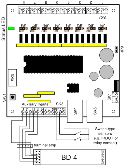
Switch type sensors (e.g a relay contact on an IRDOT) connect between the sensor terminal and terminal 12 of SK3. BD4 outputs are connected using its plug DS-1. This connects to the DAC20 SK3 as shown below. A 10 way ribbon cable from The BD4 can be simply split into strands and wired to the SK3 screw terminals as shown below. Wiring for two BD4 units is shown, but if only one is needed simply ignore the wiring for the second board.
When used to connect BD4 detectors:
| DAC20 input | DAC20 SK3 pin | 1st BD4 DS1 pin | 2nd DB4 DS1 pin |
| 1 | 2 | 1 | |
| 2 | 3 | 3 | |
| 3 | 4 | 5 | |
| 4 | 5 | 7 | |
| gnd | 1 | 2,4,6&8 | |
| 5 | 6 | 1 | |
| 6 | 7 | 3 | |
| 7 | 8 | 5 | |
| 8 | 9 | 7 | |
| gnd | 1 | 2,4,6&8 |
Programming the DAC20
The DAC20 inputs need to be selected to generate sensor messages. This is done using a programming track. Follow the instructions in your DAC20 manual for programming operations. There are two sets of CVs that need to be programmed to make the DAC20 inputs act as sensor inputs: the “Input Trigger” CVs and the “LocoNet Message” CVs. These are as follows:
| Input | Input trigger CV | LocoNet message CV |
| 1 | CV15 | CV30 |
| 2 | CV16 | CV31 |
| 3 | CV17 | CV32 |
| 4 | CV18 | CV33 |
| 5 | CV19 | CV34 |
| 6 | CV20 | CV35 |
| 7 | CV21 | CV36 |
| 8 | CV22 | CV37 |
| A | CV23 | CV38 |
| B | CV24 | CV39 |
| Required value for sensor message generation | set to 48 | set to 1 |