Typically optical sensors are used to give train position reports, but can be used for other purposes.
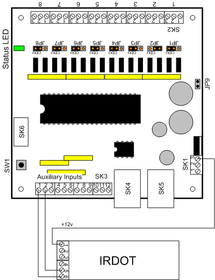
Connecting the IRDOT
The IRDOT "LED" output is used. it connects to one of the DAC20 inputs of SK3 (pins 2-11). The IRDOT ground should go to board ground (SK3 pin 1).
The IRDOT can be powered as follows:
- By a +12-18v DC "Aux" supply wired to the DAC20 SK1 pin 3, as shown.
- For one or two IRDOTS only, connect to SK3 pin 12.
- Otherwise you will need to use a separate power supply for them. Connect its 0v to IRDOT pin 6, and +12v to IRDOT pin 1.
Programming the DAC20
The DAC20 inputs need to be selected to generate sensor messages. This is done using a programming track. Follow the instructions in your DAC10 manual for programming operations. There are two sets of CVs that need to be programmed to make the DAC10 inputs act as sensor inputs: the “Input Control” CVs and the “LocoNet Message” CVs. These are as follows:
| Input | Input control CV | LocoNet message CV |
| 1 | CV41 | CV51 |
| 2 | CV42 | CV52 |
| 3 | CV43 | CV53 |
| 4 | CV44 | CV54 |
| 5 | CV45 | CV55 |
| 6 | CV46 | CV56 |
| 7 | CV47 | CV57 |
| 8 | CV48 | CV58 |
| A | CV49 | CV59 |
| B | CV50 | CV60 |
| Required value for sensor message generation | set to 2 | set to 1 |
Programming the DAC10
The same arrangement will work with a DAC10. The DAC10 inputs need to be selected to generate sensor messages. This is done using a programming track. Follow the instructions in your DAC10 manual for programming operations. There are two sets of CVs that need to be programmed to make the DAC10 inputs act as sensor inputs: the “Input Trigger” CVs and the “LocoNet Message” CVs. These are as follows:
| Input | Input trigger CV | LocoNet message CV |
| 1 | CV15 | CV30 |
| 2 | CV16 | CV31 |
| 3 | CV17 | CV32 |
| 4 | CV18 | CV33 |
| 5 | CV19 | CV34 |
| 6 | CV20 | CV35 |
| 7 | CV21 | CV36 |
| 8 | CV22 | CV37 |
| A | CV23 | CV38 |
| B | CV24 | CV39 |
| Required value for sensor message generation | set to 48 | set to 1 |